Arduino Mega 2560
Specifications and Circuitry

I'm a Multan, Pakistan based Mechanical Engineer. I push pixels, shuffle data, and slap my keyboard until everything works.
1. Overview
Arduino Mega 2560 is a microcontroller board based on the ATmega2560.
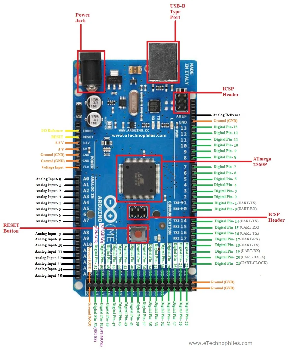
It has 54 digital input/output pins (of which 15 can be used as PWM outputs), 16 analog inputs, 4 UARTs (hardware serial ports), a 16 MHz crystal oscillator, a USB connection, a power jack, an ICSP header, and a reset button.
 |
| Fig.1 - Arduino Mega Specs |
2. Arduino Mega Pin Diagram
 |
| Fig.2 - Arduino Mega Pin Diagram |
Arduino Mega 2560 R3 Schematic
3. Ram/Memory
The ATmega2560 has 256 KB of flash memory for storing code (of which 8 KB is used for the bootloader), 8 KB of SRAM and 4 KB of EEPROM (which can be read and written with the EEPROM library).
4. Serial and Parallel Communication
4.1 Serial Communication
Serial Communication is transferring of data bit by bit, sequentially. This is the most common form of communication used in the digital word. Contrary to the parallel communication, serial communication needs only one line for the data transfer. Thereby, the cost for the communication line as well as the space required is reduced. USB (Universal Serial Bus) is present in every computer/mobile/devices for serial communication
4.1.1 I2C (Inter Integrated Circuit)
The I2C communication can be supported by two pins namely 20 & 21 where 20-pin signifies Serial Data Line (SDA) which is used for holding the data & 21-pin signifies Serial Clock Line (SCL ) mostly utilized for offering data synchronization among the devices
4.1.2 SPI (Serial Peripheral Interface)
The SPI is used to transmit the data among the controller & other components. Four pins like MISO (50), MOSI (51), SCK (52), and SS (53) are utilized for the communication of SPI.
4.1.3 UART (Universal Asynchronous Receiver/Transmitter)
Arduino Mega has 4 UART Serial Port (TX, RX), (1, 0), (14, 15), (16, 17), (18, 19)
TX is used to Transmit and RX to Recieve Data from other device.
 |
| Fig.3 - UART Specs |
4.2 Parallel Communication
Parallel communication is transferring of the bits in a parallel at a time. This is used where is speed is main concern than space. The transfer of data is at high speed due to no bus buffer is present. Digital and Analog Pins are used in Parallel to communicate with other devices. Where Each Pin's High/Low state defines the bit of Data. Seperate Pin/Wire is used to define a state/stream of data.
 |
| Fig.4 - Parallel Communication |
5. Digital Analogue and PWM I/O Pins
Arduino Mega 2560 has
- 54 digital input/output Pins (0-53)
These Digital Pins can be used to either ouput 5V (High) or 0V (Low) or can input High/Low state.
- Where 15 are PWM Pins (2-13, 44, 45, 46)
These PWM (Pulse Width Modulation) Pins can be used to Analog Output which is generated through digital pulses. The average due to frequency/width of pulse define the analog output/voltage less than 5V. And can be used where faster High/Low switching is required.
- 16 analog inputs Pins (A0 - A15)
These Analog input Pins can be used to detect input signals from 0V-5V (0-1023)
6. Current/Voltage Limitations
- Operating Voltage: 5V
- Input Voltage (Barrel Jack): 6-20V
- DC Current I/O Pins: 20mA
- DC Current 3.3V Pins: 50mA
The Arduino Mega2560 has a resettable polyfuse that protects your computer's USB ports from overcurrent. If more than 500 mA is applied to the USB port, the fuse will automatically break the connection until the short or overload is removed.
7. ICSP Header
The ICSP (In-Circuit Serial Programming) header can be used to program the Arduino board’s firmware with the new functionalities. Or if your internal arduino programmer is not working you can use seperate programmer or another arduino board to program your microcontroller.
 |
| Fig.5 - ICSP Header |


